Wavelength Selection, Band Pass, Minus, And Notch Filters
Wavelength Selection Filters
Wavelength Selection, Band Pass, Minus, And Notch Filters
Wavelength Selection Filters: have many names and operate differently. But, the intent is to select or remove one or more wavelengths, for a particular interest.
Most of the Band-Pass filters are designed either by combining Long-Wave and Short-Wave Pass filters (Broad-Band) or by utilizing Fabry-Perot Multi-Cavity Designs approach (Narrow- Band). The inverse of this is to stack quarter waves with alternating extreme high and low indices of refraction to create a Minus Filter (Broad-Band) or stack quarter waves with slightly different high and low indices creating a Notch Filter (Narrow-Band)
Transmission Band-Pass Filters are usually divided in two groups, Broad-Band or Narrow-Band Pass Filters. Although there are no Bandwidth values that define Narrow or Broad Filters in the UV, Visible, or IR, it is common to consider filters that have a Bandwidth of 2% or less of the central peak wavelength as a Narrow Band Pass. Thus, according to this convention, the Band-Pass filter centered at 500nm is considered as a Narrow-Band if the Pass Band has a Bandwidth of 10nm or less. Band-Pass Filters are defined by the Bandwidth or Full Width at Half Maximum Transmission(FWHM). Where the 50% Peak-Transmission points are defined for each rising and falling slope. It is also necessary to specify the rejection zones(Band Width about either side of the Pass-Band). In addition, the slope of the Transmission curve on both sides of the Pass-Band can be defined together with so-called Cut-On and Cut Off points. The Cut-On and Off point are both 5% of Tmax(from left to right)
Band-Pass Filters are traditionally thought only to be deposited by means of Sputtering Technologies. But, with tighter controls, than ever, we have been able to pull our 50nm FWHM in to 25nm FWHM. But, for example, for the common Telecom Dense Wavelength Division Multiplexing(DWDM) of 10nm FWHM we still defer to Sputtering. Given the extraordinary costs of that technology, many customers find what we have to offer an inviting alternative and suitable for their requirements.
Reflecting Band-Filers are another option. Specifically, there are Multiple Reflection systems, Color correcting, Laser line blocking, Minus, and Notch Filters to help enhance or reject wavelengths. For example, in vacuum ultraviolet, below 200nm or above 9µ where very few materials transmit, a Transmission Band Pass is virtually impossible. One solution is to utilize a multiple reflector filtering system where incident radiation is reflected from each surface in the system, thus, resulting in exponential filtering of the out-of-band spectrum.

Wavelength Selection Filters- BP, Minus, Notch
Below are some featured Coatings where customers wanted to select a discrete wavelength while simultaneously blocking out unwanted light that would interfere with their detection system

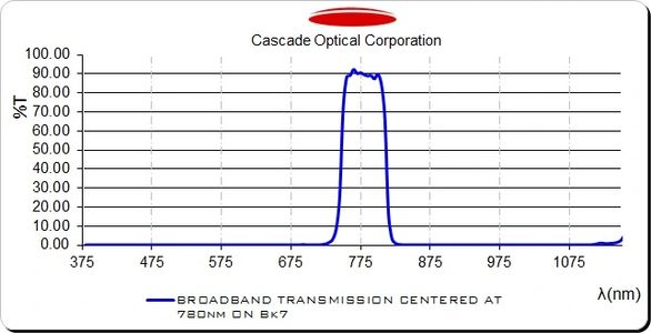
Transmission Band Pass @780nm T>80% 780nm; Tavg< 1% 200-1140nm; T=50% 748 and 810nm; T=5% 735 and 819nm Cut On/Off
This customer required a 780nm and 850nm Transmission Band Pass on D263 0.1mm thick. Unfortunately, traditional Schott Blocking Filters did not help as they rely heavily on their thicknesses. This customer is utilizing these filters to assist with virtual military staged simulations. On this incredibly thin material we were able to block out the VIS and a good portion of the NIR while yielding excellent transmission at 780nm
NASA/CASCADE CIV 157 Or Lyman Birge Hopfield Line:
Transmission Band Pass Coatings are virtually impossible here. Without exceptional controlling systems, these types of coatings already have a tendency to "crash" at the transmission point. So, adding absorption into the equation simply results in disaster.
A 4 "bounce" multiple reflection notch filter that has a custom "effective" quarter wave stack, known as π multi-layers, with the ratio of L/H=1, increases the Efficiency of the S/N ratio by an astonishing improvement of 6 orders of magnitude

ESO/CASCADE 10.6µ LWIR:
The above multiple reflection filter system was once again revisited in 2013, in order to contend with the opposite end of the spectrum. Here the customer required the filter to block out K, L, M and above 10.6µ. Since many materials absorb after 9µ and the blocking band is incredibly wide we, recommended an IR version of the above UV multi reflection system. Although more reflections are obviously better, due to space constraints, in their system, they were only able to accommodate 2 "bounces". But, given the graph to the right even 2 bounces, considerably, helps the S/N ratio
Submit Specifications below:
Cascade Optical Corporation | 1225 E hunter Santa Ana Ca 92705 | sales@c-optical.com | (714) 543-9777
Copyright © 2023 Cascade Optical Corporation - All
